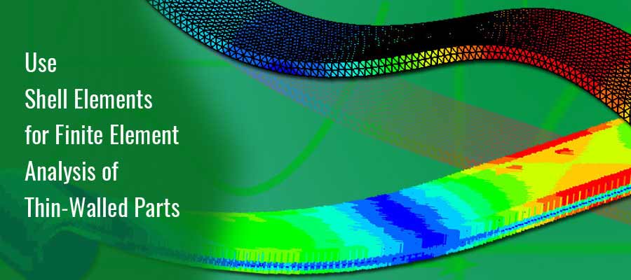
Use Shell Elements for Finite Element Analysis of Thin-Walled Parts
Posted by Rohan Belhe on November 15th, 2016

Performing finite element analyses using shell elements for thin-walled parts is often the best approach to save computational time. However, it is equally important to have good knowledge and experience with using shell elements to avoid erratic results from simulation. This is necessary because stresses in shell elements are captured differently as compared to solid ones.
Thus, as an engineer it is important to consider few important points to implement shell elements properly for structural stress analysis,
- Identification of using the data generated by simulation results
- Accuracy and limitations of stresses generated in shells
- Requirement of nominal stress
- Identification of the need of local stresses for fatigue studies
- Impact of bolted or welded region on stresses
- Determination of using forces and moments instead of stresses
The stress generation varies drastically based on the plotting method chosen, even if identical models are utilized. As such, it is important to determine the accuracy and limitations of plotted stresses. For example, using shell models at intersection between two plates creates an overlap effect, resulting into stiffness inaccuracy. To avoid this, the shell nodes can be shifted from the mid-plane to top or bottom of the surface. However, this will not negate the effects of stress singularity.
The Need for Nominal Stress
Nominal stresses are often useful to eliminate the influence of singular stress in cases where the loading is not cyclic and the goal of the simulation is to study the capacity of the plate/wall. These stresses are evaluated using element centroid stresses. However, since stresses at the centroid are generated only between the integration points in each element, it is easy to plot the entire connection without the requirement of non-physical averaging. For nominal stresses, usually coarse mesh is used.
Importance of Local Stresses for Fatigue Studies
It is important to have accurate stress results when the objective of the simulation is to estimate the fatigue life. One can use 3D brick model in cases where the stress is maximum at joints, in order to capture accurate stress concentration values. To achieve this, shell-to-solid sub modeling is utilized during the simulation.
Using Forces and Moments for Bolted or Welded Regions
Designing is better achieved when using forces and moments in cases where the plate assembly is welded or bolted. In many structural design cases, the only inputs required are forces and moments in the format of in-plane and out-of-plane forces and moments respectively.
Thus, instead of using solid elements, shell elements for thin-walled parts are the best approach to perform simulation runs faster. However, it is important to use this approach carefully, considering the goals required to be achieved through simulation. This will ensure that the results gained are accurate and meaningful to take design decisions confidently and quickly.


