Using Shell Elements for Your FEA Simulation
Posted by Bhaumik Dave on May 1st, 2015
The results of finite element analysis hugely depend on the type of element used to convert the geometry into smaller elements. While in most 3D simulations, solid elements are required, it is found that these elements do not give desired results for thin and slender structures.
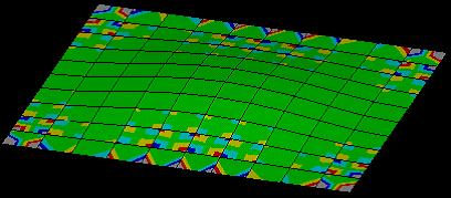
Solid elements particularly have three transitional degrees of freedom at each node. While these DOFs are suitable to evaluate bulk solid structures, for thin walls these elements have locking tendency while transferring the results of bending effects to adjacent element. This causes the stress and strain distribution to distribute unevenly, causing drastic variations in the results. Such problem can be resolved by refining the mesh with more number of elements, but it will consume more computational time.

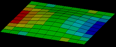
Shell elements on the contrary are ideal for such applications, which apart from simulating the bending effects more accurately; also consume less computational power compared to solid elements.
Shell elements are suitable for think structures having thickness at least 20 times than the span. These shell elements are geometrically 2D but spatially 3D, which means they are suitable for 3D thin to moderately thick structures. Beam elements can also be applied together with shells in structures consisting of long slender beam or truss type structure.

Leading FEA software such as ANSYS also offers an additional 3D solid-shell element which is both geometrically and spatially 3D and performs well for wide range of thicknesses for plate structures. It combines the benefits of shell and solid elements together, producing better results without the cost of additional computational power.
To utilize shell elements, it is required first to extract surfaces from 3D solid model and determine regions requiring beam and shell elements. It is also important to enter the correct physical property to define the thickness since shell elements assume that the stress varies linearly from top to bottom.
It is certain that the extraction time required to convert the 3D geometry into 2D surface model for shell elements and 1D for beam elements require sufficiently long time, there is a substantial savings of computational power during the solving process.


